First I mocked up the lights with a piece of black plastic to see what it would look like. This allowed me to work out the measurements before I cut the metal.


The first part to be built was the retracting mechanism for the fog and reverse lights. I had previously removed the rear wiper motor from my Maestro before it was scrapped, this was perfect as it had the 90 degrees of movement that I needed. Of course I had to unsieze it first. The mechanism needed to stop at both ends of the travel, so I binned the original park position and fitted 2 new limit switches to the mechanism.


Now for the science bit. This control box was made from 5 used relays, an old plastic box and some second-hand wire. Four years at university must be good for something. The box looks a bit wet in the photo because I'd just spilled beer on it. Circuit diagram.


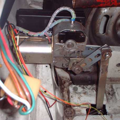
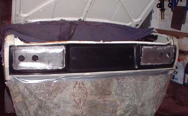
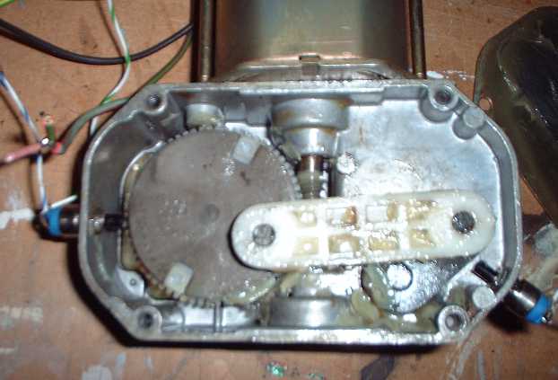
The motor isn't waterproof so it's mounted in the boot, and operates the lights via a control rod. The motor incorporates a worm drive, so it locks the position when the power is off - this locks 
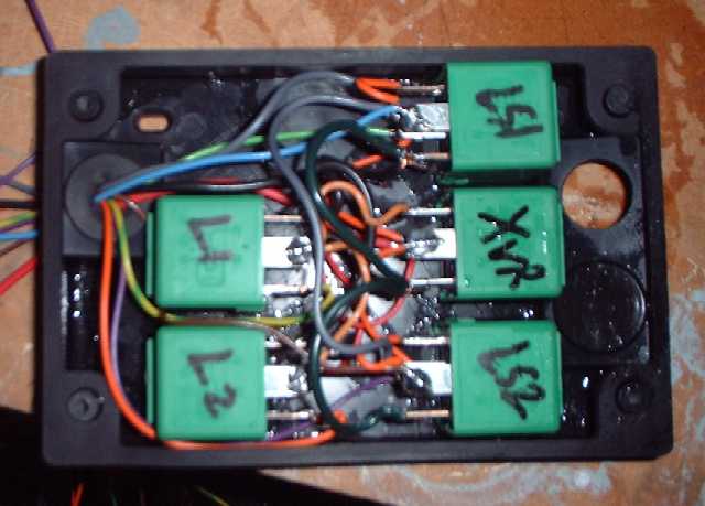
the lights in the up or down position. In this picture the motor and control box are mounted in the boot. The mounting is made from Dexion offcuts, old scrap, and bits of the old Maestro motor mount, and is attached onto the bumper mount bolts.


The lamp bracket is made from a Dexion offcut welded to some 8mm studding. The mounting brackets are bits of old workbench, and come complete with an 8mm tapped hole at either end. They are cut and welded to make 90 degree bends. The 8mm studding runs in the threaded holes, so it can rotate a quarter turn but is fully located. The gap between the lamps is deliberate, it allows the lamps to fold up without fouling the central rib of the boot floor.


The control arm is a piece of old loft ladder. The top pin is from parts unknown, but at the bottom I used an 8mm bolt and nylon locking nut. This keeps the fixing narrow so the hole in the boot floor can be smaller. The hole will be sealed up with a flexible gearstick gaiter, once I get a chance to visit the breakers yard.


Once the retractor was complete and tested, I could get on with the bodywork. Steel panels were cut to shape - in this picture I'm working on the circular cutouts for the rear lamps. All the marking out is done on the back of the panel.


Each panel was welded in place. I experimented with runs of weld but it blew holes in the metal, so on the real panel I just used spot welds. In this photo one of the panels is half done.


In this pic both sides are welded and the welds ground back ready for filling. The car is masked up for painting, and to stop welding splatter.


Before the filling and painting, I checked the lights fitted and wired up the connectors.


And that's all! I didn't take any pictures of the filling, I was too busy sanding! The filling was pretty easy because I made a lot of effort to line up the new panels properly, and made sure the welds were fully ground back. To see the final result, click here.


Pictures : John
Tile: John


Copyright 2004 Bad Design Inc